STANDARD
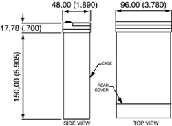
DIMENSIONS
 Figure
11-1. Standard Dimensions
|
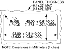
 Figure
11-2. Panel Cut-Out
|
DISASSEMBLY
You
may need to open up the meter to check or change the 115 or 230 Vac power
jumpers. You may also need to connect or disconnect serial communication
boards. To remove and access the main board, follow the steps described
in Section 3.3.
GENERAL
INFORMATION
Programmable Functions
Rate (frequency) and
totalizer
Scale Factor
-99999 to 999999 with a choice of 6 decimal point positions (9.9.9.9.9.9.),
multiply or divide
Offset
-99999 to 999999 with a choice of 6 decimal point positions (9.9.9.9.9.9.)
INPUT
CHARACTERISTICS
Maximum Frequencies
Inputs - Square Wave, (0 to +5 V)
30 kHz: S1-5 open
S1-1 and S1-4 closed
Maximum Input Voltage
Signal
S1-6 and S1-7 open
60 V rms, input protected to 120 V rms; S1-7 closed: 18 V rms S1-6 closed:
15 V rms
Maximum Input Voltage (all other inputs)
0 to 5 V
Minimum Signal
25 mV, rms (S1-3 closed)
Trigger Slopes
Positive or Negative, select by S1-8
External Gate and Reset Levels
Low level = less than 0.8V
High level = more than 3.5V
Input Impedance - Signal Input (S1-6 and 7 open)
243K pull up to excitation voltage if signal is between 0 and excitation
voltage.
External Gate and Reset Inputs
20k pull up to +5 V
DISPLAY
Type
6 digit, 7-segment, LED
Display Digit Height
14.2 mm (.56 in) Symbols: -.8.8.8.8.8. and 8.8.8.8.8.8.
Decimal Point
6 positions; programmable; Fixed or auto-range
Leading Zeros: Blank
Overflow Indication
Shows in rate or total mode; in exponential format to 9.99 E9
Update Rate
3 readings per second (unless modified by RS-232)
Displayed Value
(Measurement ╖ Scale Factor) + Offset 11.6
TIME BASE
Internal Clock Reference
921.6 KHz
Stability: ▒2 ppm/░C
Fine-Calibration Method
Programmable calibration value accessible through RS232 communications.
Requires frequency calibrator to calibrate the meter
Calibration accuracy at 25░C: ▒10 ppm
RATE
FUNCTION
Frequency
range
0.5 Hz to 30 KHz. The meter utilizes exponential format above 6 digits.
9.99 E9 signifies maximum display.
Unit of Measurement
Rate: Hertz (Scale Factor = 1)
Accuracy at 25░C
▒1 LSD ▒0.01% of the input (0-5 V (square wave) input)
TOTALIZER
Count direction
Up or Down (determined by sign of scale factor)
Internal count capacity
(500,000,000,000) input pulses. The display utilizes exponential format
above 6 digits.
9.99 E9 signifies maximum display.
AC power failure provisions
You may store the display value in nonvolatile memory and restore
with power (in totalize mode only).
ANALOG
OUTPUT OPTION BOARD
Max Load Impedance for Current Output:
500 ohm
Resolution: 15 bits
Accuracy, 0-10V:99.8%
Accuracy, 4-20 mA: 99.75%
Response Time
Total Mode: 80 mSec (99% of final value)
Rate Mode: 360 mSec (99% of final value)
RELAY OUTPUT OPTION BOARD
2 Form "C" on/off relays. Configurable for latched
and unlatched by software.
Max Current: 5Amps, resistive load.
Max Voltage: 250Vac or 28Vdc
POWER
AC voltage (standard):
115 or 230 Vac ▒15%
Frequency: 49 to 63 Hz
Power consumption: 11.5 W, max.
External Fuse Protection Recommended
AC 115V: IEC 127-2/III, 100mA, 250V (T Type) or UL Slow-Blow 125mA,
250V
AC 230V: IEC 127-2/III, 50mA, 250V (T Type) or UL Slow-Blow 1/16
Amp, 250V
Excitation Output (Select by S1-1 and S1-2)
5 V @ 50 mA maximum
8.2 V @ 70 mA maximum
12.4 V @ 100 mA maximum
For excitation currents more than 50 mA, the ac voltage must be 115
or 230 Vac ▒10%.
DC Power/Battery backup
7.5-13 V, 30 mA (typical), without any option board. The display goes
blank, but the meter continues to totalize.
260 mA is required to maintain the front-panel digital display. Add
180 mA for analog output board, 120 mA for relay board, 20 mA for RS-232
board.
ENVIRONMENT
Operating Temperature: 0░ to 50░C (32░ to 122░F)
Storage Temperature: -40░ to 85░C (-40░ to 185░ F)
Relative Humidity: 90% at 40░C (non-condensing)
MECHANICAL
Panel cutout: 1/8 DIN 3.62" x 1.78" (45 x 92mm)
Weight: 1.27 lb (575 g)
Case material: Polycarbonate, 94 V-O UL rated
|